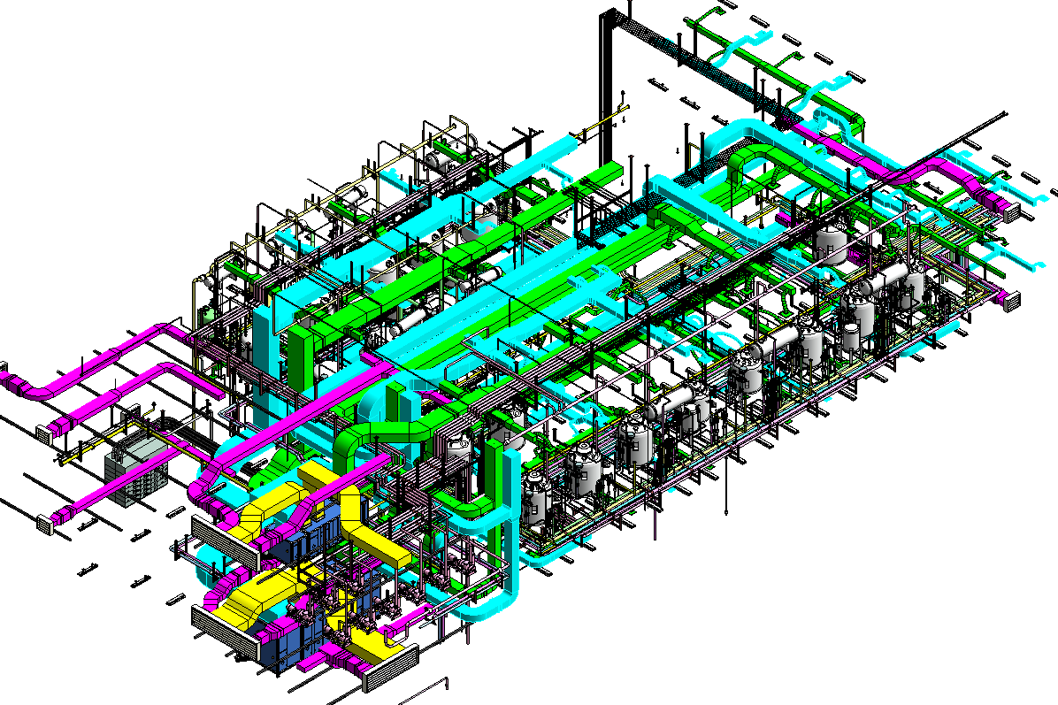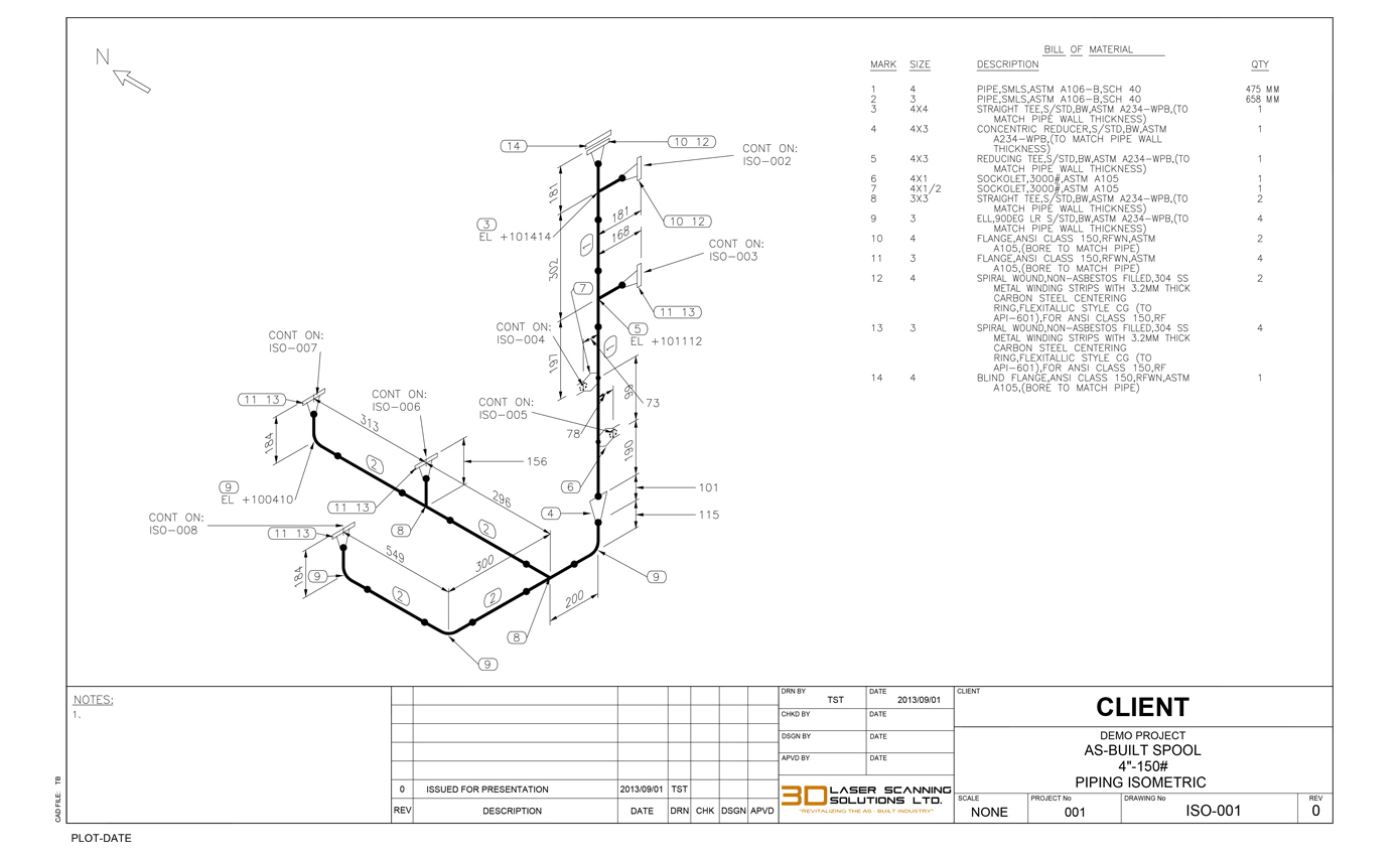

The line number indicates the fluid service, piping class and material, insulation details etc.

Indicating the line numbers for pipe runs clearly within the drawing. It shows the straight lengths of all the pipe runs on the drawing as clearly as possible. The combination of the two systems creates a productive collaboration from which machine and plant manufacturers benefit. Isometric drawings typically portray a graphical representation of the 3D piping system. Both products are among the market leaders in their fields and offer an outstanding price-performance ratio. The basic software is ISOGEN® from the market leader Alias (Intergraph). Smap3D Isometric exports all information about the 3D pipelines and creates the isometric drawing fully automatically. Usually, piping isometrics are drawn on preprinted paper, with lines of. Smap3D Isometric for Autodesk Inventor, Solid Edge® and SOLIDWORKS® An isometric drawing provides a three-dimensional layout of the equipment and piping. For the creation of piping isometrics we offer the integrated solution Smap3D Isometric for Autodesk Inventor, Solid Edge® and SOLIDWORKS®. Isometrics can easily be generated leveraging the Isogen® technology from ALIAS (Intergraph). We close the gap between plant, equipment and machine construction.

It is much less expensive than the traditional planning systems. Our Plant Design solution is easy to install and operate. This type of drawing shows the pipeline NOT to scale and simplified with all contents and all dimensions in length, width and height, with the major axes of these three dimensions intersecting at the angle of 60°. The iso is a technical drawing in the form of an isometric representation for the production of pipelines. The third element of the typical process chain in plant construction is isometric drawings.


 0 kommentar(er)
